
| Home | Products | Prices | Directory | Order | Contact | New | Books | Files | Links | Other |
DT102 RS-485/232 Mini-Terminal.
| Bottom of Page |
2-Jun-1999
Now Available $15AUD for the PCB.
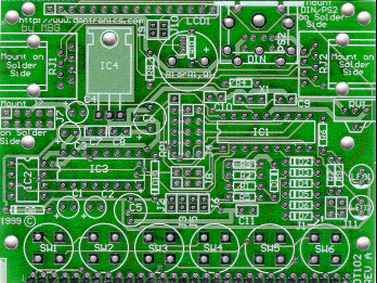
The DonTronics DT102 PCB has been designed on a 2.5" SimmStick platform, and is same size as the DT205 Relay board.
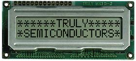
It has provision for six "Hat Key" type push button switches, and a standard 2 by 16 LCD. The board is designed for the Truly brand LCD, however many others will fit the standard 16 pin header strip provided. Mounting holes are provided for the Truly display which mounts via female/male header pins on the component side of the board, and above components such as the PIC16F84 micro. Yes, the micro will fit in a socket if need be, right under the display. The display is very simply removed.
Two RJ-45 connectors allow RS-485 communications via an 8 wire standard cables. Two jacks means RS-485 can be used on multiple connections or drops. These RJ-45 PCB mount jacks need to be mounted on the solder side of the board.
Also on the solder side of the board, you will find a spot to mount a 5 pin DIN PCB connector, same as the one in your standard PC. This allows an "AT" type keyboard to be plugged in as an alternative to the 6 push button switches.
Other features:
Max-232 and single wire comms will be catered for to some degree. Details
to be available in the future.
Configuration jumpers for various programmed feature selections.
On board Piezo buzzer
PIC16F84 4Mhz crystal or resonator operation. (PIC16C61 and others
can be used)
LCD contrast control.
Powered from RS-485 bus or SimmBus.
Power ON LED
Debugger LED and link. (RS-485)
Termination resistor and link. (RS-485)
On board +5V regulator and support circuitry.
Special notes regarding the circuitry used.
The keypad matrix uses a technique described on the microchip website.
http://www.microchip.com/10/Appnote/Category/12CXXX/Logic/4_012/index.htm
Configuration jumpers ( J4 ) use another multiplexing technique. Essentially when the PIC needs to read the configuration jumpers the i/o port is configured to be an input and the 'E' ( RA2 ) pin is configured to be an output with a logic low. The configuration information is then obtained by reading the appropriate input ports. The resistor pack bias resistors ( RP1 ) for the configuration jumpers are needed to prevent any interaction between the normal functions of the i/o lines and the configuration jumpers.
In 'normal' operation ( when not reading the configuration jumpers )
either the PIC or the LCD would be driving the i/o lines. The bias resistors
common line is connected to the 'E' ( RA2 ) line to make sure that the
correct
voltage levels are present on the i/o lines during all phases of operation.
Serial communications.
There are three possible hardware interfaces for the serial communications
to and from the DT102.
At the time of writing, software isn't available to make use of the
"AT" keyboard input, however code can be found at Steve Lawther's site
at: http://ourworld.compuserve.com/homepages/steve_lawther/keybinfo.htm
This may need to be re-configured to suit the DT102 board. Code can also
be found at Mauricio Culibrk's site at: http://www.arne.si/~mauricio/PIC.HTM
Steve Lawther's "AT Keyboard/LCD" Schematic
Other Software will be available and full details will be announced
in the near future;
Here are some of the specifications:
LCD software specs.
Functionally similar to Peter Andersons http://www.phanderson.com/PIC/ser_lcd_kit.html
and/or Ben Wirz http://www.wirz.com/sli-oem/docs/sli-oem.pdf
exceptions are the baud rate is limited to two different rates, only one
type of display is supported ( should be able to cope with 16, 20 or 40*2
).
Baud rates either 2400 or 9600, jumper selectable.
Either rs232/rs485/logic, jumper selectable. ( 485 and logic may be
in second release )
Addition of 6 way keypad and ability to read from keypad and from LCD.
Will use 'spare' function codes among the 'FE' sequence to access.
Read / Write to EEProm.
Self test mode ( pressing particular keys on reset enters test mode
)
Demo test software to run on PC?
DonTronics SimmStick and other PCB Prices can be found at:
http://www.dontronics.com/postpcb.html
DonTronics now have dealers in many countries. These dealers can be
found at:
http://www.dontronics.com/dealer.html
Board Components:
1 by DT102 PCB
20-Jun-99
Haven't found the time just yet to put together the parts list, however
one minor problem has been found with this PCB.
The tracking and signal connections appear to be completely correct.
Diodes D8 and D10 are listed as 1N4004's, but the hole sizes are too small to mount these. You can do many things to overcome this problem. We have found 1N4001's will fit, but these may be awkward to find. You can "Surface Mount" the diodes, or use resistor legs soldered to the board to "T" solder the diodes to. A neat job should be acheivable without too much drama.
Function of D8
Protect the polarity of the PWR input signal, and to "Direction Isolate"
the PWR signal to the RJ-45 +12V so that two 12 Volt inputs don't interact.
If no power input is used on the RJ-45 bus, then D8 can be a wire link.
Function of D10
Almost the opposite description of D8. J2 pads can be used to short
out D10, so that power can be fed from the SimmStick bus to the RJ-45 bus.
If power is fed up the RJ-45, then D10 can be shorted out with a wire link.
OK Don,
Not wanting to dampen any enthusiasm :)
1. Holes for 1N4004 diodes are too small (at least the diodes I had) D8, D10
2. Holes for RV1 are too small to take an open frame trimpot, though they would probably fit with a more expensive cermet type trimpot
3. Holes for J2, J3, J, J6, J9, J10 are too small to take standard
square jumper posts. Also, the spacing between the two posts on each
of these jumpers are a than .1" apart, so I had to break apart header strips
to fit them in. Standard shorting jumpers don't fit, so I wire wrapped
them.
------------------------
Circuit designer feedback:
All of the jumpers mentioned are what I would consider 'build time'
configuration jumpers. I wouldn't expect anyone to need change them after
construction, wheras the jumpers that can take the 0.1" header are 'run
time' jumpers. YMMV
Rod Egan
Bloke what was responsible in some part for all of this! <grin>
-----------------------
Other than that, I hope to finish the Atmel link tonight. If
I can find a digital camera, I will send a pic.
Regards
Barry Hay
Sage Telecommunications wrote:
>
> Just out of interest did you guys actually get an RJ45 from Jaycar?
The
> samples that I sent were from Altronics. I checked the Jaycar catalogue
and
> there is no specs for the RJ45 connecters that I can see.
> The Altronics RJ's have the same footprint as Molex, which is pretty
much a
> standard footprint.
> And both the right angle and 'straight' RJ45's had the same footprint.
> The odd one out appears to be the Jaycar one!
> Rod
Yes, I did go to Jarcar and get them, I have been assured that the footprint
has changed since I got them. Good old Jaycar!
Don...
(These are Australian companies, however Rod has mentioned that Molex has the same footprint.)
FYI,
The following distributors have RJ45's with the same footprint as the
Altronics samples used for the DT102 PCB layout.
XON / Prospec part number is TS2K88
Farnell part number 257-102
Molex part number 95009-2881
Rod
to be updated::::::::::::::::::::::::::::::::::::

| Home | Products | Prices | Directory | Order | Contact | New | Books | Files | Links | Other |

mailto: don@dontronics.com_
Copyright © 1996-99 DonTronics
| Top of Page |
